TeleMetrum
This is a recording dual-deploy altimeter for high power model rocketry with integrated GPS and telemetry link.
For the latest TeleMetrum firmware and related ground station software, please visit the AltOS page on this site.
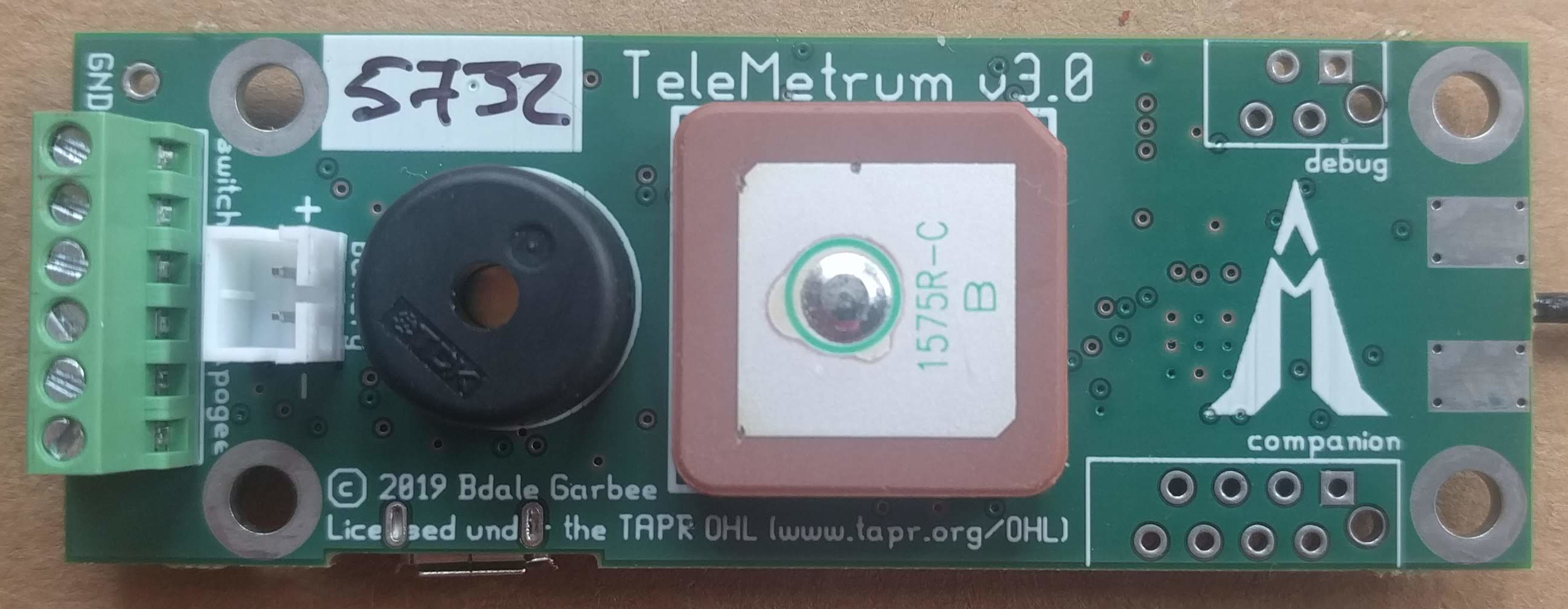
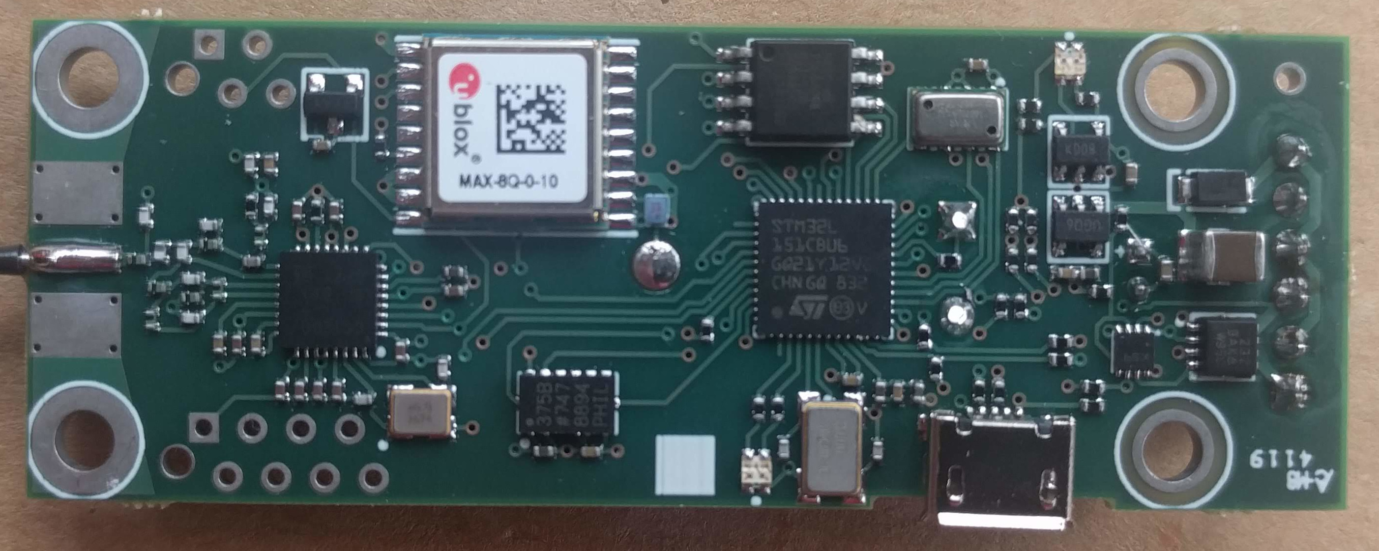
These are photos of previous production version 3.0, we'll try to get around to taking some v4 photos eventually:
v4.0 was introduced in 2023, and is now available for sale.
Features
User View
- Recording altimeter for model rocketry
- Supports dual deployment (can fire 2 ejection charges)
- 70cm ham-band transceiver for telemetry downlink
- Barometric pressure sensor good to 100k feet MSL
- 1-axis 200-g accelerometer for motor characterization
- On-board, integrated GPS receiver
- On-board non-volatile memory for flight data storage
- USB for power, configuration, and data recovery
- Integrated support for LiPo rechargeable batteries
- Uses LiPo to fire e-matches, can be made to support separate pyro battery
- 2.75 x 1 inch board designed to fit inside 29mm airframe coupler tube
Developer View
- Hardware Features of v3.0
- Atmel SAMD21G17D ARM Cortex M0+ based Microcontroller
- TI CC1200 Low Power, High Performance RF Transceiver
- 150mA 3.3V LDO regulator
- Winbond W25Q64CV serial flash memory
- u-blox MAX-8Q GPS receiver
- on-board passive patch antenna
- async serial interface
- Measurement Specialties MS5607 Micro Altimeter Module
- Wide range — 120kPa to 1kPa (approximately -1500m to 31000m)
- High precision — 2.4Pa resolution (approximately 20cm at sea level)
- Factory calibrated.
- Analog Devices ADXL375 3-Axis Digital MEMS Accelerometer
- +- 200g full-scale
- on-chip digitizer
- Software Features
- Written mostly in C with some ARM assembler
- Runs from on-chip flash, uses on-chip RAM, stores flight data to serial flash
- USB serial emulation for "console" interface
- Tools Used
- Lepton EDA for schematic capture
- pcb-rnd for PCB layout
- Licenses
- The hardware is licensed under the TAPR Open Hardware License
- The software is licensed GPL version 2
TeleMetrum v4 early units shipped with uBlox MAX-M8C GPS modules, but we had a low yield on those boards for some reason. Newer units have the MAX-M10S GPS module.
Videos
There are a number of TeleMetrum customer and other videos on YouTube
Artifacts
There is a single manual for TeleMetrum and all other Altus Metrum products, which is available in html and pdf formats.
An outline of the board with drill hole locations is available in pdf format.
This board was designed using lepton-eda and pcb-rnd.
The hardware design files are available from git.gag.com in the project hw/telemetrum.
Work on the next version proceeds on the master branch, with occasional temporary branches created when Bdale is making some major / speculative change. Branches/tags with names like 'v4.0' document what we're actually flying on the respective PCB revisions.
For those who don't have ready access to the gEDA suite, here are pdf snapshots of the files for Production PCB version 4.0 in more easily readable form.
Rockets we know of flying with TeleMetrum boards have exceeded 50g acceleration, been well above Mach 1, and reached altitudes greater than 25k feet AGL with great results. Keith's second generation ground station program called AltosUI works on Windows, Mac, and Linux systems and logs telemetry to disk, displays current and max values for key parameters during flight, includes voice synthesis during the flight so that our eyes can stay on the rockets, and even includes live display of rocket position over moving maps! After flight, altosui can extract the complete flight log from TeleMetrum, can display plots of the data from either the telemetry received by radio or the onboard flight log, can output a kml file for use with Google Earth, and can also output all the flight data as a csv file for easy import to spreadsheet programs or other analysis tools allowing you to perform whatever custom analysis you can envision! More details on the software, including full source code and pre-built packages can be found on the AltOS page on this site. Feel free to download the software and try it before purchasing our hardware!